motogadget m.unit blue install & rewire for a Buell XB12SS
Our customer approached us in January 2020 with a request to install a motogadget system to his beloved Buell XB12SS.

Having extensively modified the Buell himself, our customer initially asked if we could attend at his home to complete the wiring, as he really did not want the Buell to leave his sight.
Our customer having had several major motorbike smashes in the past while a despatch rider, has had to have his right shoulder fused, this coupled with other complications, has meant that the Buell build has become a bit of a lifeline for him, a place for him to absorb himself away from the challenges he faces day to day. With this in mind, we whole heartedly understood why he was keen to not let the Buell out of his sight.
However, through many conversations, building a rapport & plenty of email & verbal dialogue along the way; our customer realised that Daniel would, as with all of the motorcycles which come through our doors, treat his Buell with the utmost respect. We even went as far to promise that no other motorcycles, (apart from our own), would be booked in during the time the Buell was with us.
We can now hear from Daniel Morris – Master Motorcycle Technician & Motorcycle Wiring Expert about the processes him & our customer went through during the motogadget install & rewire.
“To commence a project like the Buell XB12SS motogadget install, we needed to undertake bit of forward planning. This has begun to get a bit easier, as we have completed several motogadget installs to date now.
Therefore, during the initial conversations with our customer, one of the modifications he asked us to implement, was to relocate the ECU to under the false tank cover (which on this model is the airbox) with the motogadget m.unit sitting above it.
Our customer also sent me a copy of the Buell’s wiring diagram. This is critical part of the puzzle for the project to move forward. We have completed a rewire on a previous project without a wiring diagram; but it added at least 5-6 hours on top & here is why.
Sitting down on a damp Sunday afternoon I studied the engine management wiring diagram, drawing out the wires I needed to just make the Buell run. I ended up with a skeleton loom with around six wires that would need to go to the battery, fuse box or m.unit to supply power to the ECU & consumers.
We kept in the wiring from the ECU to the dash, as we were going to use the beautiful motogadget chrono classic speedo. The wires include the supply to the dash for engine management warning, oil pressure, indicators, high beam etc.
With the wiring diagram drawn out we awaited the Buell to arrive from “Secure Bike Mover”. Once the Buell had safely arrived, we strapped the Buell down on the ramp so we could check it over before removing the original loom.

First, we checked everything worked & then inspected the loom wiring colours. Great news the colours matched! (They don’t always!)
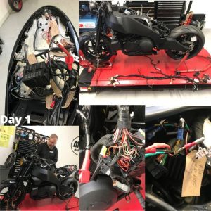
Day 1. With the seat & airbox removed we started to remove the original loom from the Buell. It was quite tight, but with a bit of wiggling the original loom was gently removed & laid out on the bench.

Day 2. The next morning the first job was to mark up & un-wrap the original loom. We recently invested in a label printer which is capable of printing on to heat shrink, making clear safe labelling of each wire. This is a massive help, as even the simplest fuel injection loom runs in excess of 40 wires, so it’s easy to loose track without having everything marked up correctly.
Unwrapping the original loom & starting at the front working back to the fuse box; we were able to start removing the unwanted wiring.

First up were the indicators & headlight wires, heading backwards to the fuse & relay box. Once at the fuse box I consulted my wiring diagram confirming the feed wires to the ECU. These were then cut & labelled so we could connect them to the new fuse box later. This process was then repeated for each circuit.
With the original loom now half the size & now being the bare bones to run the Buell; it was loosely laid back in place so we could mark the loom as we needed to shorten it by around 30cm at the ECU plugs, due to its new location.
This process was quite time consuming as there was 43 wires that needed cutting, soldering & heat shrinking. This process cannot be rushed as each wire had to be cut & staggered, so the loom didn’t bulge in one place when taped up. It was then wrapped with loom tape ahead of day three.
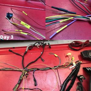
Day 3. Starting day three & eight hours done so far, the first thing to do was finish tidying the loom & start laying in the wiring for the motogadget m.unit & lights.

Once the wiring circuits were laid the loom was loosely cable tied together. Checking back to the diagram ticking off each wire to make sure nothing was missed. The loom was then taped & heat shrunk where the loom could be seen. Where possible the loom was braided, this is not only for appearance, but it is also very hard wearing so helps to stop the loom from sustaining any damage.
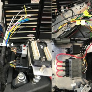
Day 4. Day four began with me refitting the loom back in the frame & the injection system was then plugged back in. There was a plastic section that holds the loom away from the engine. This was refitted, along with the fan.

We had to drop the rear shock out to make sure none of the wires would drop down on to the hot exhaust when the Buell was ridden. We also ran the power lead to the rear for the m.unit & made a short earth strap to mount from the m.unit to the frame.
We then ran the rear subframe wires through some braid, before bolting the rear subframe back on.
Day 5. Next, we placed the battery in (the red battery in the pictures is only for the mock up & testing), & fitted a 4 way fuse box.
The fuse box only needed to be small, as it is only used for protection of the power supplies to the ECU & charging circuit. We had 4 wires that needed to be fused. Fan supply, ECU supply, Fuel pump & a 30amp for the charging system. All the other circuits are protected by the microprocessor inside the m.unit. (We will explain a bit more about this later).
The fuse box needed a direct feed from the battery, as did the power supply to the relay for the starter solenoid. This meant hopping the power to each fuse on one side, then connecting the wire to the main power cable at the battery.

We then extended the wiring from the ECU to the diagnostic socket, which we also mounted up near the fuse box. All of these were extended to enable easy access should there be an issue when out on the road. Once this was done the earths had ring terminals added, before being bolted to the subframe.
At this point the rear lights wiring needed to also be extended & tidied up. However, we left these until the m.unit was up & running as we wanted to change the way the lights worked.
Now 24 hours in we commenced our 6th day.
Moving to the front of the bike, we started on the connections for the speedo & power to the headlight.
We knew we needed to make the loom so it could be removed for future work, so the two plugs for the dash were to be mounted up under the frame & the headlight, indicators were to be on plugs mounted inside the headlight case.
Looking at the diagram it became apparent there was no light for the engine management or low fuel level. Following a quick conversation with our customer, we decided to fit two small LEDs into the headlight shell.
First, we separated the wiring; one for headlight & one for clocks. A couple of extra wires were spliced for tell tale indicators & additional power supply. Next the wiring needed extending for the engine management & fuel warning lights, it was then heat shrunk & braided.
The head light needed to be removed to make the holes for the LEDs & while it was out, we drilled two small holes under the mounts for the indicator wires so they no longer ran down the sides. We also needed to make the hole in the bottom for the cables bigger so the plugs were able to be removed.
At this point, the speedo needed a small bracket fabricating while the headlight was out, so it could be mounted, we have left the final touches for our customer to finish & refitted the headlight shell so we can complete the build.
It was then time to get the crimps out & make up the connector boxes for both the dash & headlight. After running some power to the m.unit, the dash came to life.
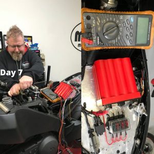
Day 7. At the beginning of the 7th day, the first thing was to pull off the bars & run the wiring though the inside of the bars & then make up some connectors so the loom could be separated should any work need to be done in the future.
Once we connected the switch gear to the m.unit we could test everything worked, including firing the Buell up for the first time.

Running through the switches everything seemed to work correctly. Fire up time. Boom! fired up first time! Hang on what’s going on here? The Buell lights came on randomly?!
After a bit of research the m.button was picking up interference from the coil when running, which looks like is a common issue. We tried moving the wires but to no avail. Nothing for it we had to wire direct from the switches to the m.unit. It was a bit of extra work, but it was no good as it was.
Day 8. At the beginning of the 8th day, the last thing to do was to configure the motogadget Bluetooth to a mobile phone to enable the lights, alarm & speed sensor to be set up.
The motogadget app allows you to set the speed with which your lights flash, the brightness of them, the sequence if you have one light doing multiple operations, you can even set the internal alarm from the app & the motorcycle will recognise you by your mobile phone.
With the blue tooth enabled & all of the operations having been set using the ‘testing battery’ the motogadget install was complete.
So, there we have it. 38 hours work in total with a complete bespoke loom, uniquely designed for our customers Buell & a full motogadget m.unit blue install to transform the Buells electrical operational capacity.”
