Yamaha XS650 Flat Tracker fully bespoke re-wire
Written by Daniel Morris, Director – mono motorcycles 2017 Ltd.
“They say preparation is everything, and that’s never truer when you’re doing a full rewire.
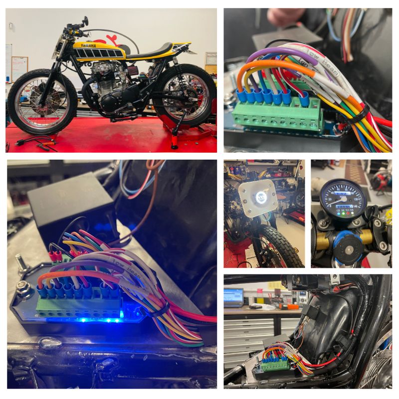
Our customer contacted us before Christmas asking us to rewire his Yamaha XS650 flat tracker he had built. It had been a running bike, but he wanted the electrics sorting as they were proving unreliable.
We spoke at length on the phone and via email and he settled on an Axle Joost B-Box to control the lighting with motogadget switches and an Antigravity 4 cell battery. As the XS is kick start we could run a very small battery. The XS already had a Vape ignition and battery less charging system fitted.
Our job was to convert the system to charge the battery and fit all the electronics and build a bespoke loom.
This is the first time I had used the Axle Joost B-box, we normally opt for the more expensive m.unit by motogadget. Although not quite as technical as the m.unit the principle is basically the same.
Therefore, my first job was to do a bit of research to find out the difference between the two. One of the major things was the way the ignition switch works. On the m.unit the ignition is powered by a 12v supply coming from a switch or m.lock back to the “lock” connection on the m.unit. When the m.unit sees voltage it switches the ignition on.
With the B-Box the ignition switch is controlled by an earth path, this means the ignition switch just sends a ground signal to bring the unit on. This means you could just have a small button instead of a switch.
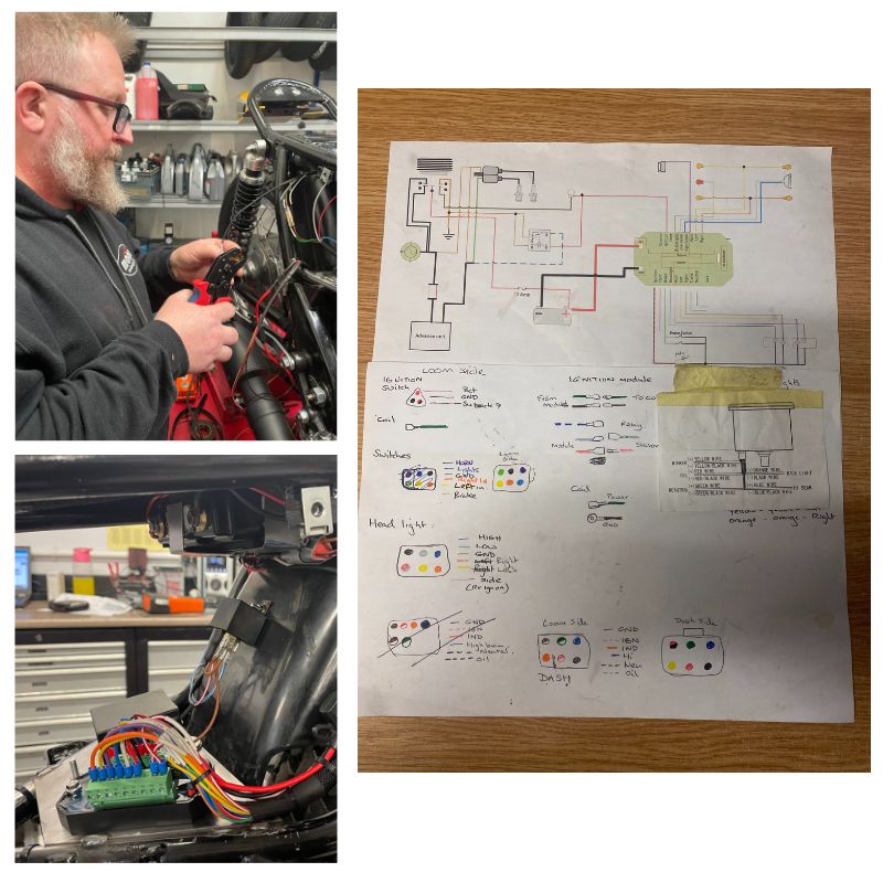
Next up was to find a diagram for the Vape ignition system, once sourced it was apparent that the kit for the battery less system is the same as the battery supplied unit it was just wired differently. During the evenings I drew a bespoke wiring diagram for the XS including the dash the customer had supplied and the Vape unit wired with a battery.
Once the XS arrived at the mono motorcycles workshop we removed the last few bits of electrical components.
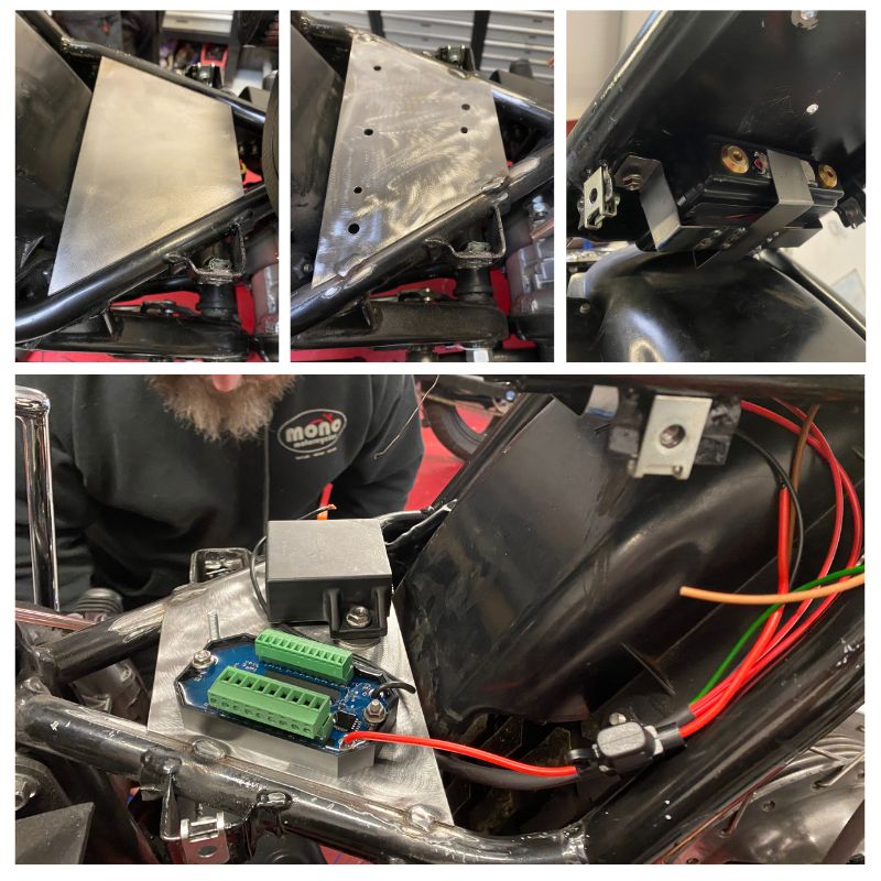
We then discussed with our customer how he wanted the B-Box mounted and with a piece of cardboard made a template to sit the extra parts on. You will not be able to see this when the bike is finished as there are two side pods which mount to the sides.
Once the template was right, this was cut out of steel and the holes were marked and drilled for the Reg/rec, ignition control and B-box. It was then welded into place.
Next job was to fabricate a bracket to hold the tiny 4 cell Antigravity battery. This was to keep the B-Box alive with voltage so it could work and store its settings. Next was to check what each wire on each component did like the headlight for instance. Each wire was then marked for example high beam wire, low beam wire and ground. This was repeated for the rear light and also for the dash.
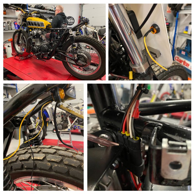
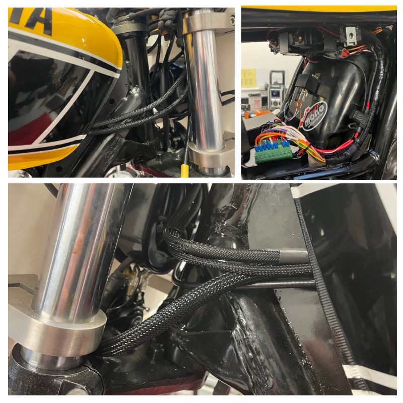
The wires all needed extending so the plugs for the loom could be hidden. Once the lighting wires had all been extended, we moved onto the charging circuit. Again, the wires needed to be extended along with the wires from the stator.
The handlebars were then drilled to mount the single momentary touch buttons and the wires were run inside the handlebars.
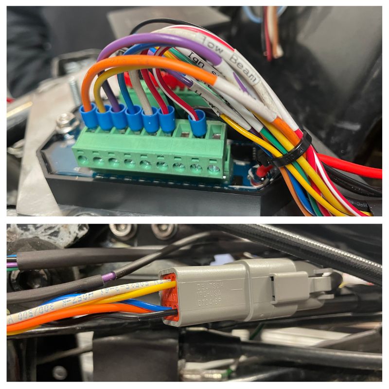
Now each component and each wire was tagged, we could start to run the wires along the frame to make the main loom.
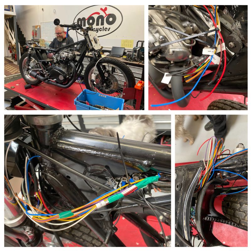
Following the wiring diagram makes this a bit easier. With the high beam and indicators, I knew I had to run a wire from the main loom which will go to the indicator lights within the dash.
We do this by stripping back a small section of wire on the main loom. Using a smaller gauge same colour wire we strip the end off and tightly wrap it around the exposed copper wire. Then we use a small amount of solder and join them together, and finally heat shrink the join. This makes a watertight joint which will withstand the load and vibration for years to come. This is repeated for each wire, until we have everything we need for the loom to work.
We have over the years tried many different connectors but by far the best are the German Deutsch type. They are fully waterproof and use a deep tight round pin configuration which can carry the loads required. These connections are commonplace on many modern cars and motorbikes. We are now only using these connectors unless space/or period type are required.
Before making the connectors, I drew a hand drawn diagram to allow me to know which wire went to which plug. This also made sure that every wire was accounted for.
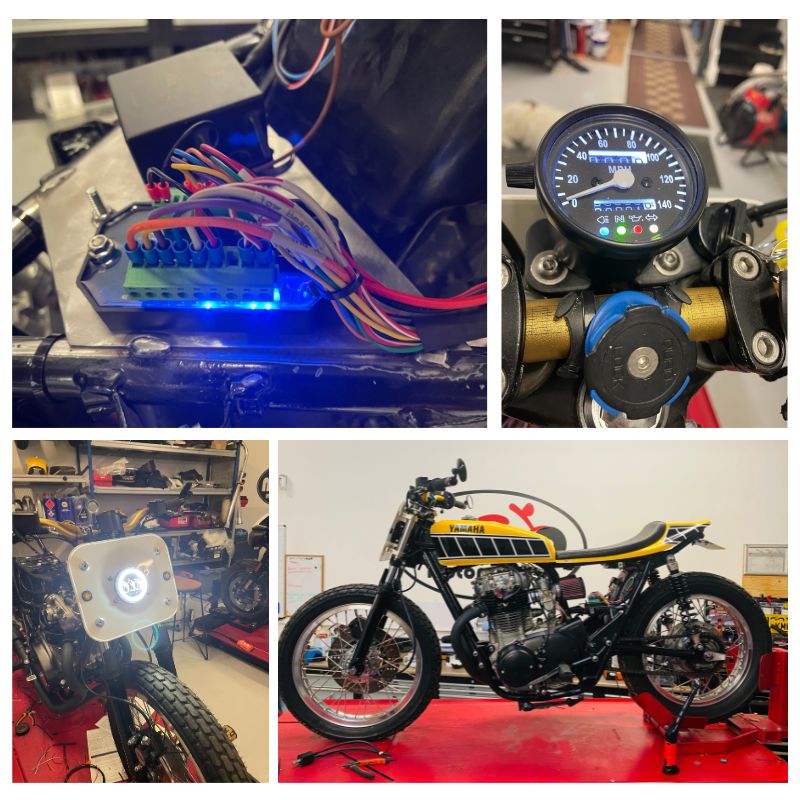
Once the connections were made, I did a full light test then checked that we had a spark with the ignition switched on and a spark that switched off with the ignition.
I then kicked the bike over to check the charge. I found that I couldn’t run the bike for very long as once it was running it was found that there was a considerable oil leak from under the bike. Under investigation, the oil leak was coming from the clutch push rod seal. As the customer had undertaken this work prior to arrival, we notified him and he advised he would remedy this upon the bikes return.
I have made sure that not only does the customer have a future proofed wiring system for the XS, a bespoke wiring diagram for him or another owner to follow, but I have also designed the bespoke loom to be easily removed through a series of connectors should the bike need painting or modifying in the future.
All told, the labour for the fabrication, the full rewire and the drawing of the bespoke wiring diagrams came in at 21.5 hours.
If you are considering a full rewire for your custom motorcycle, then please do contact us by email in the first instance giving us as much information about your project as possible. You can contact us via info@monomotorcycles.co.uk We look forward to hearing from you.”
Written by Daniel Morris, Director – mono motorcycles 2017 Ltd.